- English
- Español
- Português
- русский
- Français
- 日本語
- Deutsch
- tiếng Việt
- Italiano
- Nederlands
- ภาษาไทย
- Polski
- 한국어
- Svenska
- magyar
- Malay
- বাংলা ভাষার
- Dansk
- Suomi
- हिन्दी
- Pilipino
- Türkçe
- Gaeilge
- العربية
- Indonesia
- Norsk
- تمل
- český
- ελληνικά
- український
- Javanese
- فارسی
- தமிழ்
- తెలుగు
- नेपाली
- Burmese
- български
- ລາວ
- Latine
- Қазақша
- Euskal
- Azərbaycan
- Slovenský jazyk
- Македонски
- Lietuvos
- Eesti Keel
- Română
- Slovenski
- मराठी
- Srpski језик

Home
>
Products > Current Monitoring Unit > Residual Current Monitoring Sensor > Leakage Protection Residual Current Monitoring Unit


Leakage Protection Residual Current Monitoring Unit
Xinkong is a professional Leakage Protection Residual Current Monitoring Unit manufacturer and supplier with many years of experience. Leakage Protection Residual Current Monitoring Unit can meet many applications, If you are interested in our quality services, you can consult us now, and we will get back to you promptly.An important safety function of these devices is monitor of the leakage current of the entire system from Power modules against earth. A defective system can become dangerous for people or cause fires. Before it comes so far, Power modules must be disconnect from the grid. The leakage current contains DC and AC components. Therefore an AC/DC-sensitive monitoring unit is necessary.
Model:XKCA-01-MD
Send Inquiry
Product Description
Xinkong is a Leakage Protection Residual Current Monitoring Unit manufacturer and supplier, well-known for quality service. Wenzhou Xinkong Import & Export Co., Ltd. is an innovative enterprise integrating scientific research, production and sales. The company's sales network covers many countries and regions such as Europe and Southeast Asia, and its product quality and service are well received by customers. You can rest assured to buy Leakage Protection Residual Current Monitoring Unit from us.
The XKCA Series Residual Current Detection Module is widely applicable, especially in public charging stations for electric vehicles, electric motorcycles, electric bicycles, charging fees, and power safety management. It offers simple usage and easy installation.
Features
■ Single Supply +5 V
■ Dual digital open-drain output, 20mAAC/6mADC trip indication
■ 3-phase primary conductors on module (typ. 32A, max. 40A)
■ PWM output for DC residual current value indication (0~30mA)
■ Error output for system fault indication
■ Mounted on PCB board
■ Self-test function
Applications
■ Ground fault detection
■ Electric vehicle charge station
■ Converter leakage current detection
Standard
■ Applicable for IEC 62752 residual current requirements
■ Applicable for IEC 62955 residual current requirements for RDC-PD
■ Applicable for UL2231 residual current requirements
■ Components designed full-fill RoHS/REACH
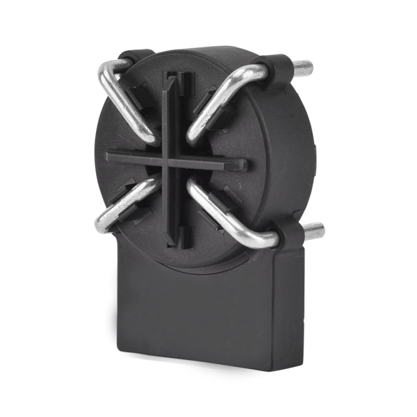
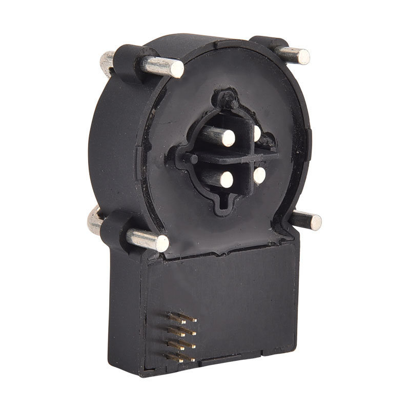
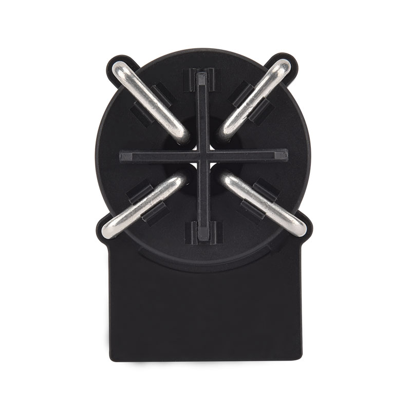
Product Apperance
Typical Application Schematic:
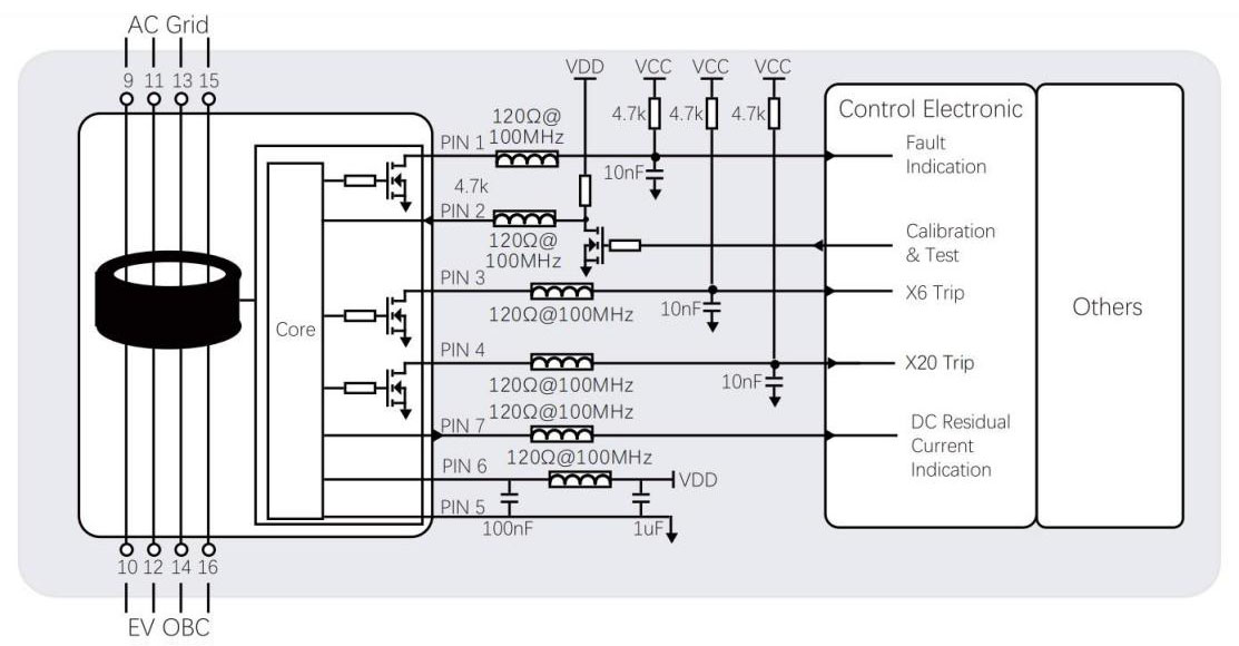
Pin Definition:
| Pin-No | Pin Name | Function |
| 1 | Error |
■Open-collector output pin for indicating the system fault condition ■When no system fault, this pin will be conducted to GND ■When system fault occured, this pin will be high-impedance |
| 2 | TEST-IN |
■When this pin been conducted to 0VDC, module will calculate the zero-point-drift and store the value to register in the MCU to finish the calibration operation. ■After calibration finished, system will internally generate simulated residual current, to check whether module can do the correct response. During this procedure, X20-OUT & X6-OUT will turn to high-impedance if module working correct. Attention: ■When using the TEST-IN function, the main circuit must be cut-off to ensure no residual current flow ■When using this pin function, please follow the time diagram figure |
| 3 | X6-OUT |
■If residual current exceeds pre-set DC trippling value (for this module typically 4.5 mADC), this output is in a high-impedance state ■When the total residual current r.m.s exceeds pre-set all-current trippling value, this output is in a high-impedance state ■When system-fault happens, this output is in a high-impedance state ■For other normal conditions, this output is in a low level(GND) |
| 4 | X20-OUT |
■If residual current exceeds pre-set all-current tripping value (for pure-AC typically 17.8 mAAC), this output is in a high-impedance state ■When system-fault happens, this output is in a high-impedance state ■For other normal conditions, this output is in a low level(GND) |
| 5 | GND | ■Ground |
| 6 | VDD |
■Module power supply, standard voltage 5VDC ■Voltage input required to be within 4.85~5.15VDC, power output capability > 100mA ■Power supply ripple ≤ 150mV (It is suggested to use LDO circuit, for reference IC LP2985A-50DB) |
| 7 | PWM |
■Indicating DC residual current component with duty-cycle with 8kHz PWM ■Output resolution = 3.33%/mADC from 0~30mADC ■Accuracy about ±0.5mA |
| 8 | N.C. | ■Not used |
Electrical/Reliability Characteristics:
| Char | Min | Typ | Max | Unit | |
| 1 | Primary nominal RMS current (1phase / 3phase) | 32 | 40 | A | |
| 2 | Supply voltage | 4.85 | 5 | 5.15 | V |
| 3 | Ambient operation temperature | -40 | +105 | ℃ | |
| 4 | Ambient storage temperature | -20 | +65 | ℃ | |
| 5 | Static Power Consumption | 110 | mW | ||
| 6 | Electrical clearance;Primary-Primary | 6.5 | mm | ||
| 7 | Electrical clearance;Primary-Secondary | 10 | mm | ||
| 8 | Creepage distance;Primary-Primary | 8 | mm | ||
| 9 | Creepage distance;Primary-Secondary | 10 | mm | ||
| 10 | Voltage input, low level | 0 | 0.6 | V | |
| 11 | Voltage input, high level | 4.2 | 5 | V | |
| 12 | Theoretical design life | 20 | Yr | ||
| 13 | Operating altitude | 4000 | m |
Trip-Current (residual current related characteristics):
| Wav | Freq | Min | Typ | Max | Unit | |
| 1 | AC | 50Hz | 15 | 17.8 | 20 | mA |
| 2 | A0 | 50Hz | 11 | 17 | 26 | mA |
| 3 | A90 | 50Hz | 10 | 18.5 | 27 | mA |
| 4 | A135 | 50Hz | 10 | 22.9 | 28 | mA |
| 5 | 2PDC | - | 3.5 | 5.0 | 7 | mA |
| 6 | 3PDC | - | 3.1 | 4.5 | 6.2 | mA |
| 7 | S-DC | - | 3.0 | 4.5 | 6.0 | mA |
Trip-Time (residual current related characteristics):
| Wav | Freq | Current | Typ | Max | Unit | |
| 1 | AC | 50Hz | 30mA | 50 | 1000 | ms |
| 2 | AC | 50Hz | 60mA | 16 | 100 | ms |
| 3 | AC | 50Hz | 150mA | 15 | 60 | ms |
| 4 | AC | 50Hz | 5A~100A | 8.5 | 60 | ms |
| 5 | A0 | - | 42mA | 25 | 100 | ms |
| 6 | A0 | - | 84mA | 18 | 60 | ms |
| 7 | A0 | - | 210mA | 10 | 60 | ms |
| 8 | A0+DC | - | 42mA+6mADC | 18 | 60 | ms |
| 9 | A0+DC | - | 84mA+6mADC | 15 | 60 | ms |
| 10 | A0+DC | - | 210mA+6mADC | 15 | 60 | ms |
| 11 | S-DC | - | 6mA | 48 | 1000 | ms |
| 12 | S-DC | - | 60mA | 16 | 100 | ms |
| 13 | S-DC | - | 300mA | 8.5 | 60 | ms |
| 14 | 2PDC/3PDC | - | 60mA | 20 | 100 | ms |
| 15 | 2PDC/3PDC | - | 120mA | 15 | 60 | ms |
| 16 | 2PDC/3PDC | - | 300mA | 12 | 60 | ms |
| 17 | 2PDC/3PDC | - | 5A~100A | 12 | 60 | ms |
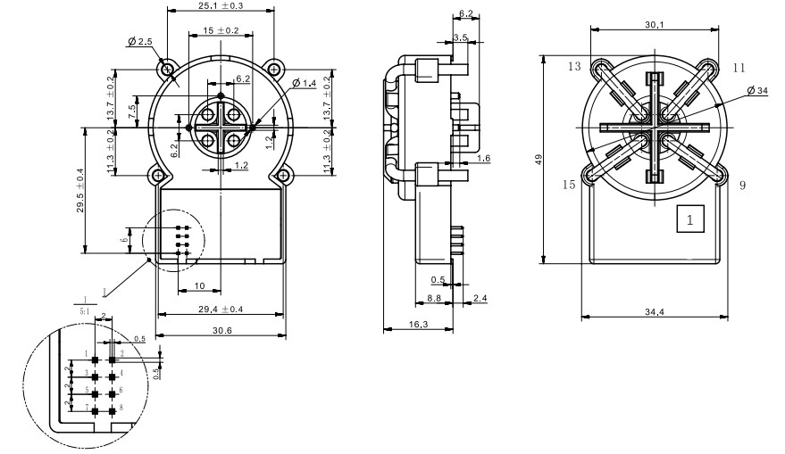
Product Dimension (mm):
Timing Diagram:
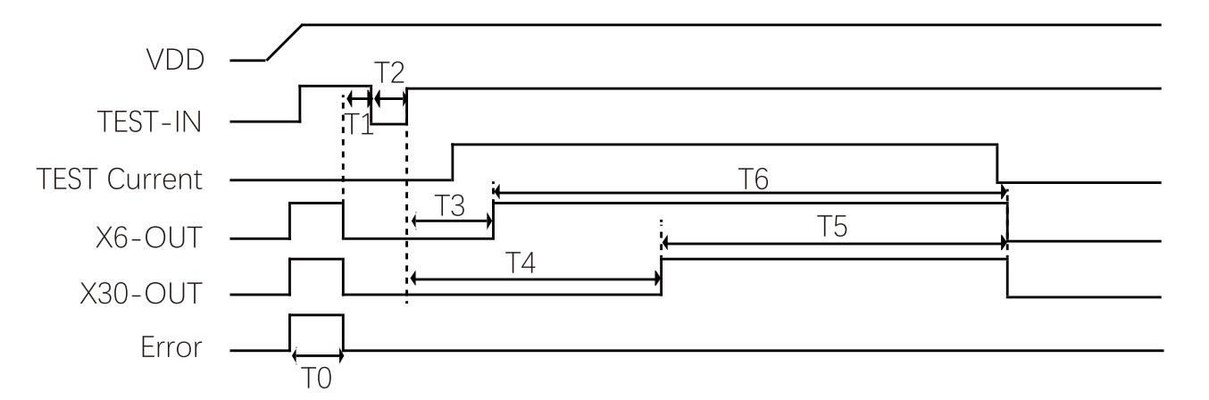
■ T0 as the waiting time for system stablization, T0≈ 270ms
■ T1 as the waiting time, it is suggested T1 ≥ 100ms
■ T2 as the calibration and self-test order time, it is suggested 50ms ≤ T2 ≤ 100ms
■ T3 as the waiting time for the self-test DC, T3≈ 200ms, it is suggested to read X6-OUT after 300ms
■ T4 as the waiting time for the self-test AC, T4≈ 690ms, it is suggested to read X30-OUT after 300ms
■ T5 as the AC self-test indication duration time, T5 ≈ 1580ms
■ T6 as the DC self-test indication duration time, T6 ≈ 1090ms
Self-Test Circuit:
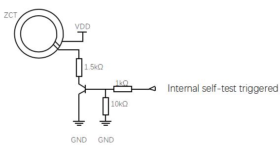
■ 2 widing on the ZCT to generate simualted DC residual current
■ By using VDD to generate typical value = 6.53 mADC simulated residual current
■ This current is the most restricted tripping condition to test whether system is working correct
Digital Signal Flip Threshold:
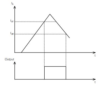
■ For avoiding the signal oscillation, tripping signal output flipping has been set with tripping threshold and recovery threshold
■ When tripping threshold  reached,the related X-OUT flip,and when the current decrease to the recovery threshold
  , the related X-OUT flip again, back to low level state
■  is set as 100% typical tripping value, and
  is set as 55% typical tripping value
Hot Tags: Leakage Protection Residual Current Monitoring Unit, China, Manufacturers, Suppliers, Factory, Made in China, Quality, Advanced
Related Category
Send Inquiry
Please feel free to give your inquiry in the form below. We will reply you in 24 hours.