- English
- Español
- Português
- русский
- Français
- 日本語
- Deutsch
- tiếng Việt
- Italiano
- Nederlands
- ภาษาไทย
- Polski
- 한국어
- Svenska
- magyar
- Malay
- বাংলা ভাষার
- Dansk
- Suomi
- हिन्दी
- Pilipino
- Türkçe
- Gaeilge
- العربية
- Indonesia
- Norsk
- تمل
- český
- ελληνικά
- український
- Javanese
- فارسی
- தமிழ்
- తెలుగు
- नेपाली
- Burmese
- български
- ລາວ
- Latine
- Қазақша
- Euskal
- Azərbaycan
- Slovenský jazyk
- Македонски
- Lietuvos
- Eesti Keel
- Română
- Slovenski
- मराठी
- Srpski језик
Home
>
Products > Current Monitoring Unit > Residual Current Monitoring Sensor > Isolation Testing B-Type Leakage Sensor


Isolation Testing B-Type Leakage Sensor
Xinkong is a professional Isolation Testing B-Type Leakage Sensor manufacturer and supplier with many years of experience. Isolation Testing B-Type Leakage Sensor can meet many applications, If you are interested in our quality services, you can consult us now, and we will get back to you promptly.An important safety function of these devices is monitor of the leakage current of the entire system from Power modules against earth. A defective system can become dangerous for people or cause fires. Before it comes so far, Power modules must be disconnect from the grid. The leakage current contains DC and AC components. Therefore an AC/DC-sensitive monitoring unit is necessary.
Send Inquiry
Product Description
Xinkong is a Isolation Testing B-Type Leakage Sensor manufacturer and supplier, well-known for quality service. Wenzhou Xinkong Import & Export Co., Ltd. is an innovative enterprise integrating scientific research, production and sales. The company's sales network covers many countries and regions such as Europe and Southeast Asia, and its product quality and service are well received by customers. You can rest assured to buy Isolation Testing B-Type Leakage Sensor from us.
Features
■ Single Supply +5 V
■ High and low level output
■ Self-test function
■ Mounted on PCB board
Applications
■ Ground fault detection
■ Electric vehicle charge station
■ Converter leakage current detection
Standard
■ Applicable for IEC 62752 residual current requirements
■ Applicable for IEC 62955 residual current requirements for RDC-MD
■ Components designed full-fill RoHS/REACH
Overview
An important safety function of these devices is monitor of the leakage current of the entire system from Power modules against earth. A defective system can become dangerous for people or cause fires. Before it comes so far, Power modules must be disconnect from the grid. The leakage current contains DC and AC components. Therefore an AC/DC-sensitive monitoring unit is necessary.
The XKCA Series Residual Current Detection Module is widely applicable, especially in public charging stations for electric vehicles, electric motorcycles, electric bicycles, charging fees, and power safety management. It offers simple usage and easy installation.
Typical Application Schematic:
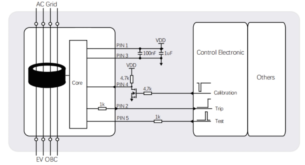
Pin Definition:
| Pin Number | Symbol | Pin Type | Functions |
| 1 | VDD | Power |
Module power supply, standard voltage 5VDC Voltage input required to be within 4.85~5.15VDC, power output capability > 100mA Power supply ripple ≤ 150mV |
| 2 | TRIP | OUTPUT | When the residual current exceeds the threshold, the output level changes from bottom to high |
| 3 | GND | Power | Ground |
| 4 | CAL | INPUT |
When this pin been conducted to 0VDC, module will calculate the zero-point-drift and store the value to register in the MCU to finish the calibration operation. When using the CAL function, the main circuit must be cut-off to ensure no residual current flow |
| 5 | TEST | INPUT | Before starting charging, perform a simulation test on the product through this pin to verify whether the product functions normally |
Electrical/Reliability Characteristics:
| Char | Min | Typ | Max | Unit | |
| 1 | Primary nominal RMS current (1phase / 3phase) | 32 | 80 | A | |
| 2 | Supply voltage | 4.85 | 5 | 5.15 | V |
| 3 | Relative Humidity | 95 | % | ||
| 4 | Ambient operation temperature | -40 | +105 | ℃ | |
| 5 | Ambient storage temperature | -20 | +65 | ℃ | |
| 6 | Power Consumption | ≤110 | mW | ||
| 7 | Voltage input/output, low level | 0 | 0.6 | V | |
| 8 | Voltage input/output, high level | 4.2 | 5 | V | |
| 9 | Theoretical design life | ≧20 | Yr | ||
| 10 | Operating altitude | ≤4000 | m |
Trip-Current (residual current related characteristics):
| Wav | Freq | Min | Typ | Max | Unit | |
| 1 | S-DC | - | 3 | 4.5 | 6 | mA |
| 2 | 2PDC | - | 3.5 | 5 | 7 | mA |
| 3 | 3PDC | - | 3.1 | 4.5 | 6.2 | mA |
Trip-Time (residual current related characteristics):
| Wav | Freq | Current | Typ | Max | Unit | |
| 1 | S-DC | - | 6mA | 100 | 1000 | ms |
| 2 | S-DC | - | 60mA | 50 | 300 | ms |
| 3 | S-DC | - | 200mA | 50 | 100 | ms |
| 4 | 2PDC | - | 60mA | 50 | 300 | ms |
| 5 | 2PDC | - | 200mA | 50 | 100 | ms |
| 6 | 3PDC | - | 60mA | 50 | 300 | ms |
| 7 | 3PDC | - | 200mA | 50 | 100 | ms |
NoTrip-Time (residual current related characteristics):
| Wav | Freq | Current | Low-limit | Unit | |
| 1 | AC | 50Hz | 30mA | ∞ | ms |
| 2 | AC | 50Hz | 60mA | 300 | ms |
| 3 | AC | 50Hz | 150mA | 80 | ms |
| 4 | AC | 50Hz | 5A | 80 | ms |
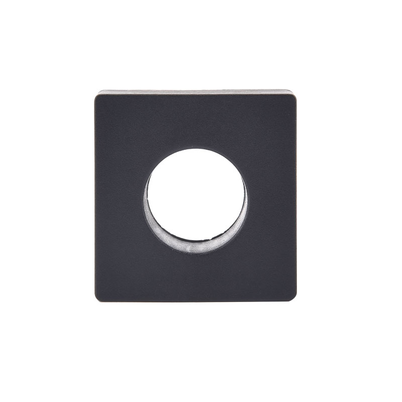
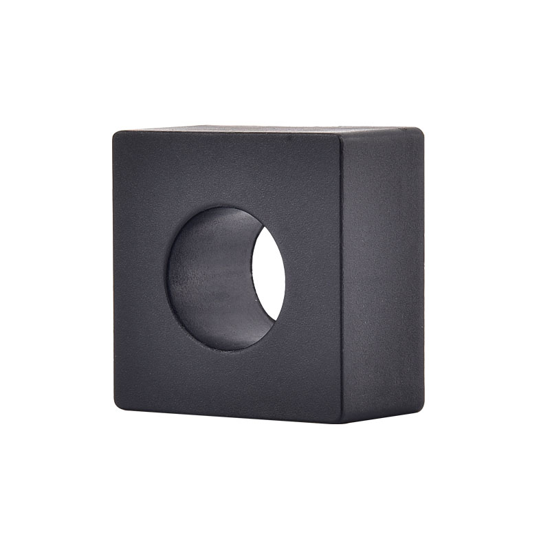
Product Dimension (mm):

Note: Terminal wires can be customized.
Timing Diagram:
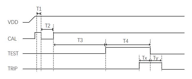
■ VDD power-up speed ≤ 5ms/V
■ T1 as the waiting time, it is suggested T1 ≥ 100ms
■ 50ms≤ T2≤100ms, cal pin low time greater than 50ms, the product begins to enter the zero phase
■ T3≥500ms and wait for the zero to complete
■ T4≈400ms, and the Test self-test signal enable must wait until T3 is complete before it can be applied
■ TRIP pin output high duration Tx = 100mS (verify self-test function)
■ Ty=100ms is the TRIP pin high level fading time (disables self-test verification)
Self-Test Circuit:
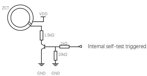
■ 2 widing on the ZCT to generate simualted DC residual current
■ By using VDD to generate typical value = 6.53 mADC simulated residual current
■ This current is the most restricted tripping condition to test whether system is working correct
Digital Signal Flip Threshold:
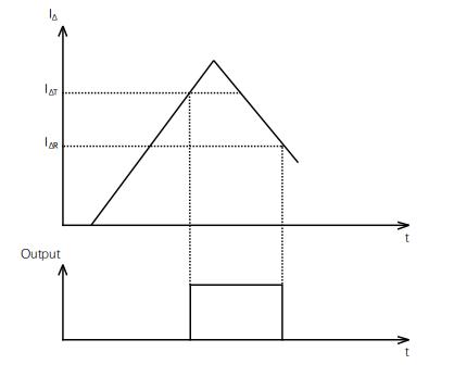
■ For avoiding the signal oscillation, tripping signal output flipping has been set with tripping threshold and recovery threshold
■ When tripping threshold reached ,the related X-OUT flip,and when the current decrease to the recovery threshold
  , the related X-OUT flip again, back to low level state
■ is set as 100% typical tripping value, and
  is set as 55% typical tripping value
Hot Tags: Isolation Testing B-Type Leakage Sensor, China, Manufacturers, Suppliers, Factory, Made in China, Quality, Advanced
Related Category
Send Inquiry
Please feel free to give your inquiry in the form below. We will reply you in 24 hours.